


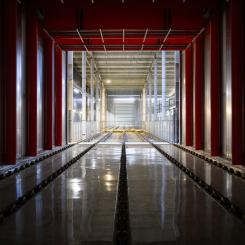
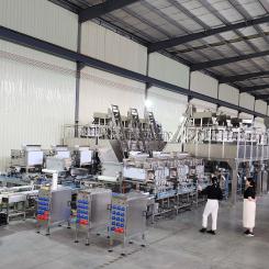
The paper industry imposes high standards in terms of productivity and plant availability.
The vast potential for energy savings that lies behind proper drainage and maintenance is key to understanding how these two aspects are very often some of the main overlooked factors, thus entailing hidden costs.
Lack of accurate vacuum measurements, analysis of partial drainage data and poor maintenance of drainage and vacuum systems - just to name a few - are some of the most common issues.
Oradoc|MTK approach to address these problems relies on a thorough on-site technical audit, in order to assess the real effectiveness of the vacuum and drainage system, highlight problems and implement an action plan aimed at reducing hidden costs.
Why it's important
The audit activity on the vacuum system is important to optimize the process from an energy point of view, in order to use only the vacuum requirement strictly necessary for correct operation, managing the various areas of the machine in the best possible way.
The punctual and optimal control of the vacuum degree also allows to obtain other benefits, in addition to energy savings: the adequate vacuum level guarantees the correct and gradual extraction of water from the paper pulp, up to the formation of the sheet, but it also ensures the necessary cleaning of the felt, which must guarantee excellent permeability conditions both to absorb water inside and to allow a better deposit to the paper fibers on its surface.
Last but not least, the revision of the vacuum system also allows to extend the useful working life of the various elements that constitute it, check the state of wear and remove any deposits.
Main activities
The main activities that are performed by our on-site technicians are:
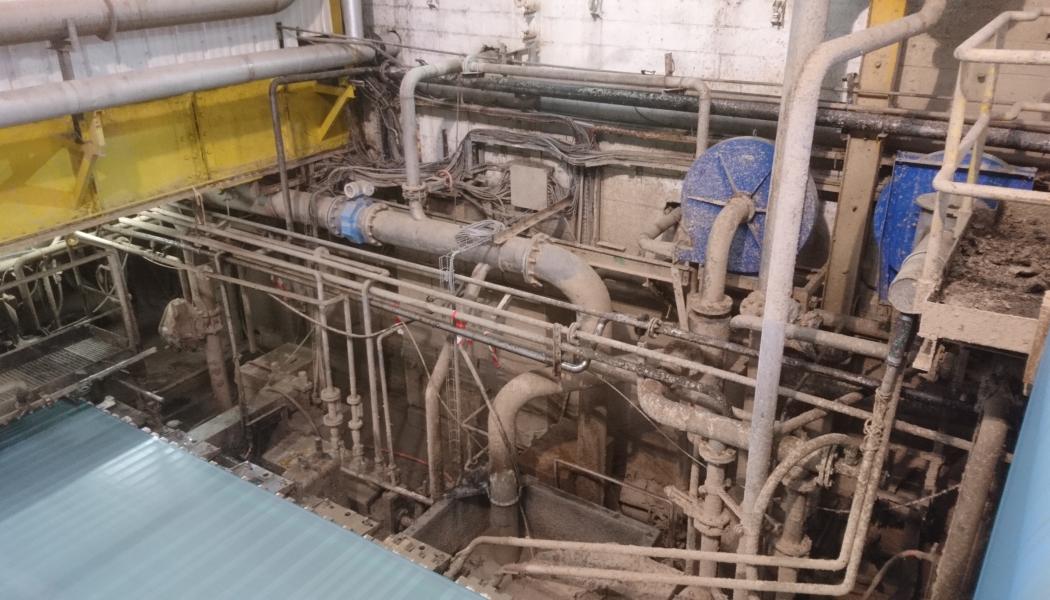
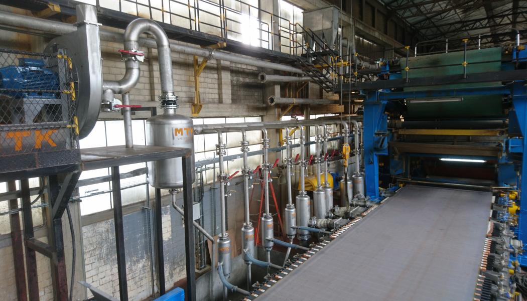
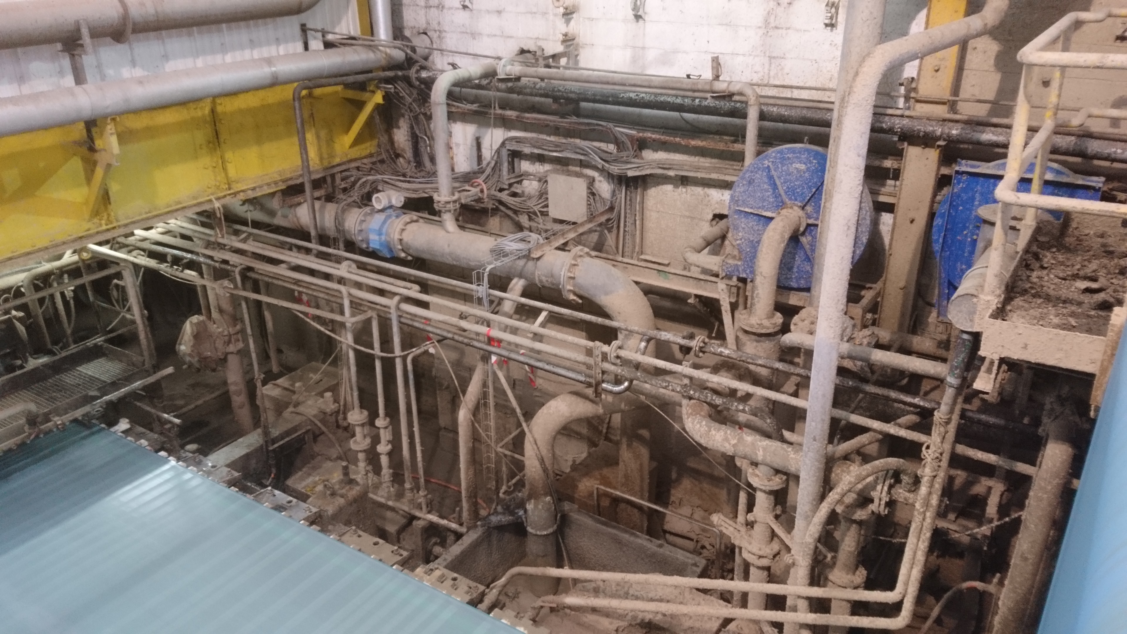
- analysis of the existing layout to look for improvement solutions, trying to reduce the length of the pipes and fittings, in order to limit as much as possible any leaks distributed along the system, in the area that goes from the suction boxes to the vacuum source (fans or pumps);
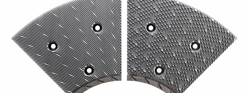
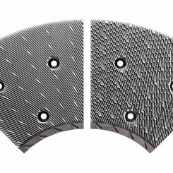
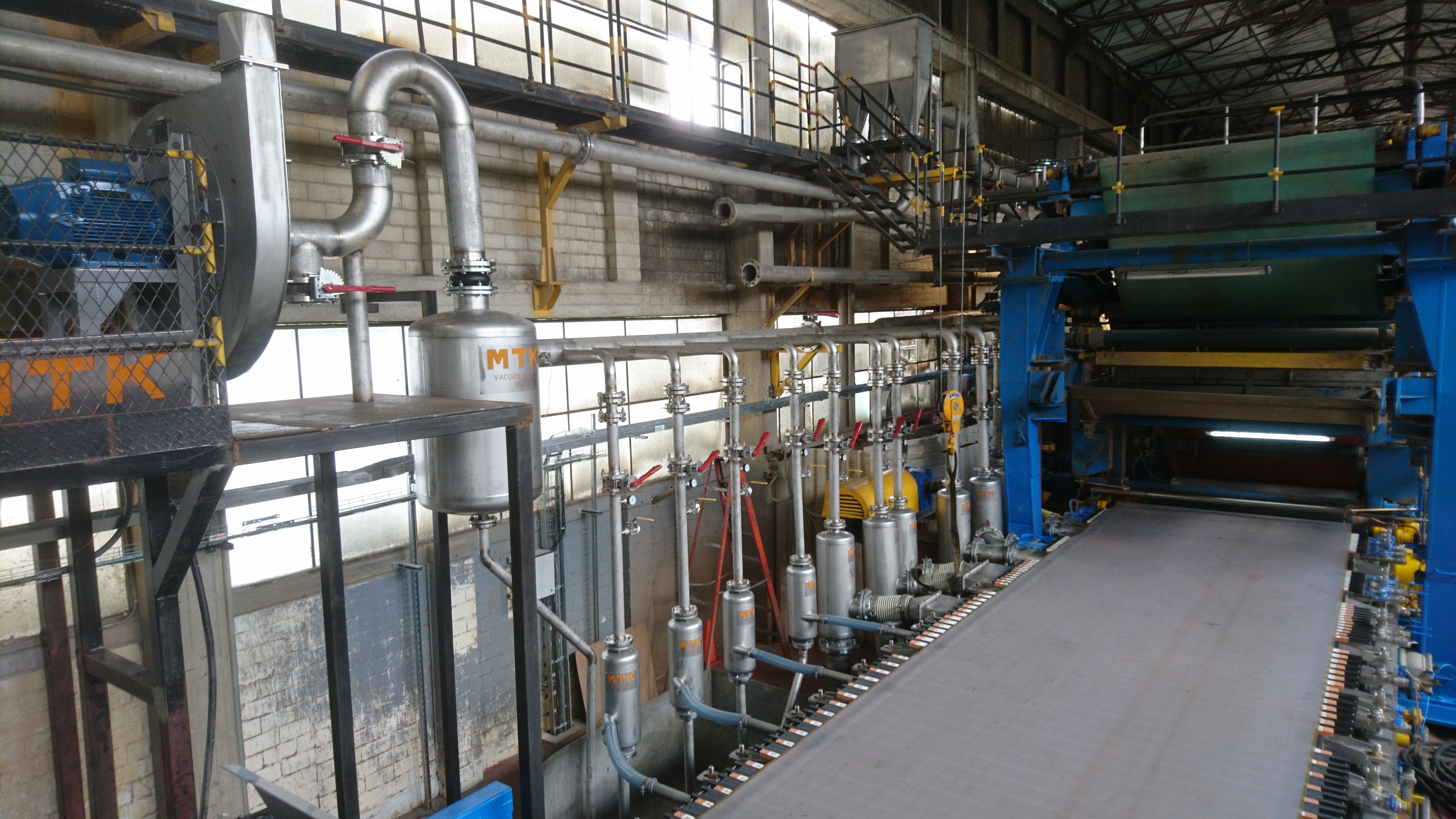
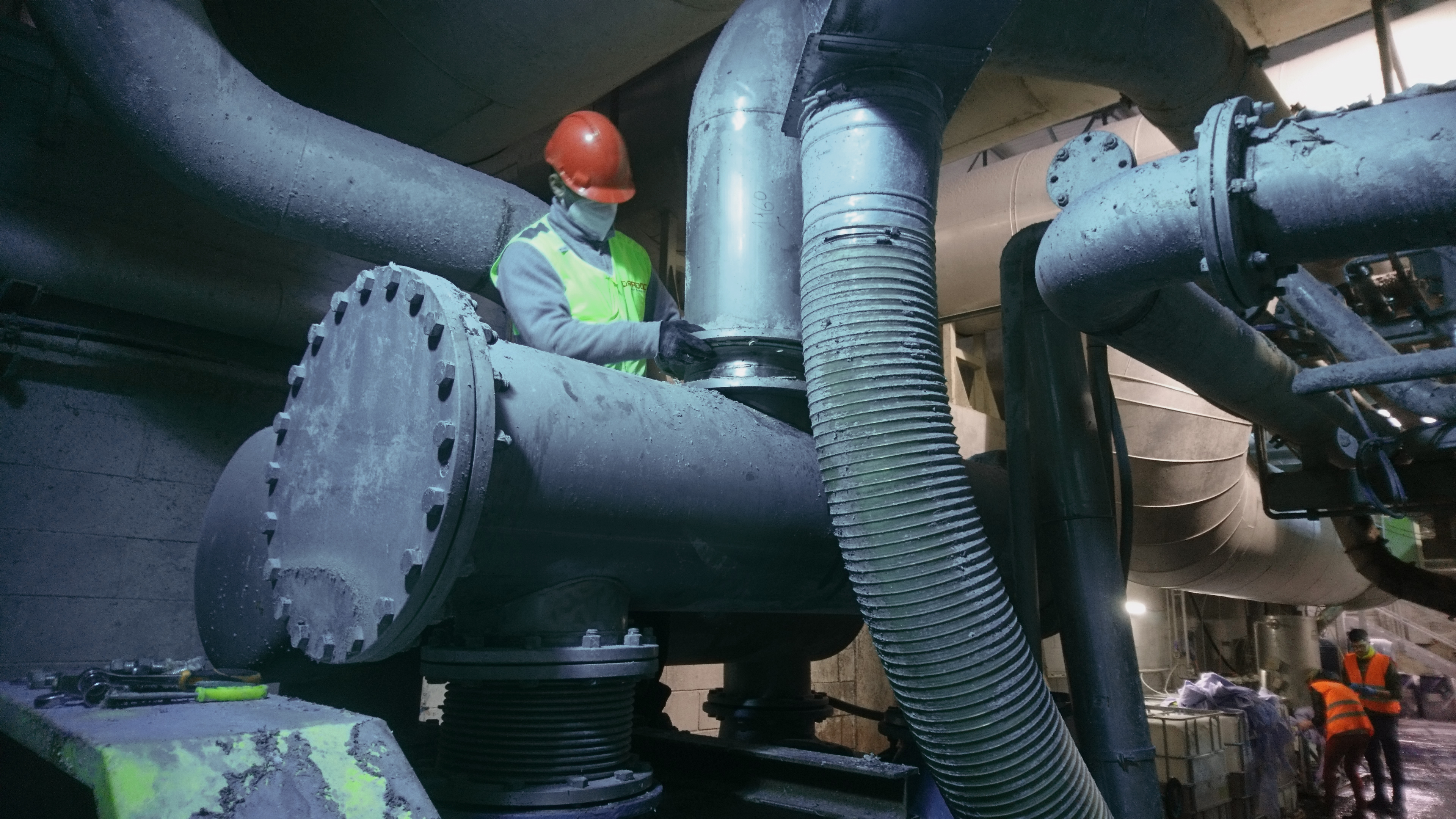
- surveys of the main elements that make up the vacuum system (air/water separators, valves, pipes, water collection tanks, pumps, fans) to verify their correct sizing;
- verification of the state of wear of the various elements that make up the system, including nozzles and impeller, pump heads and internal area;
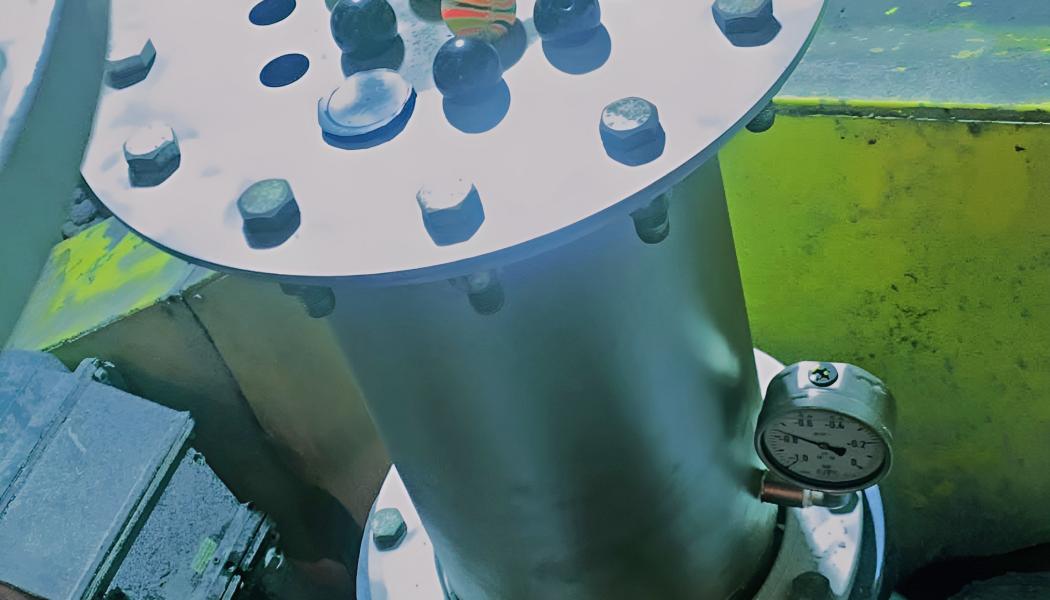
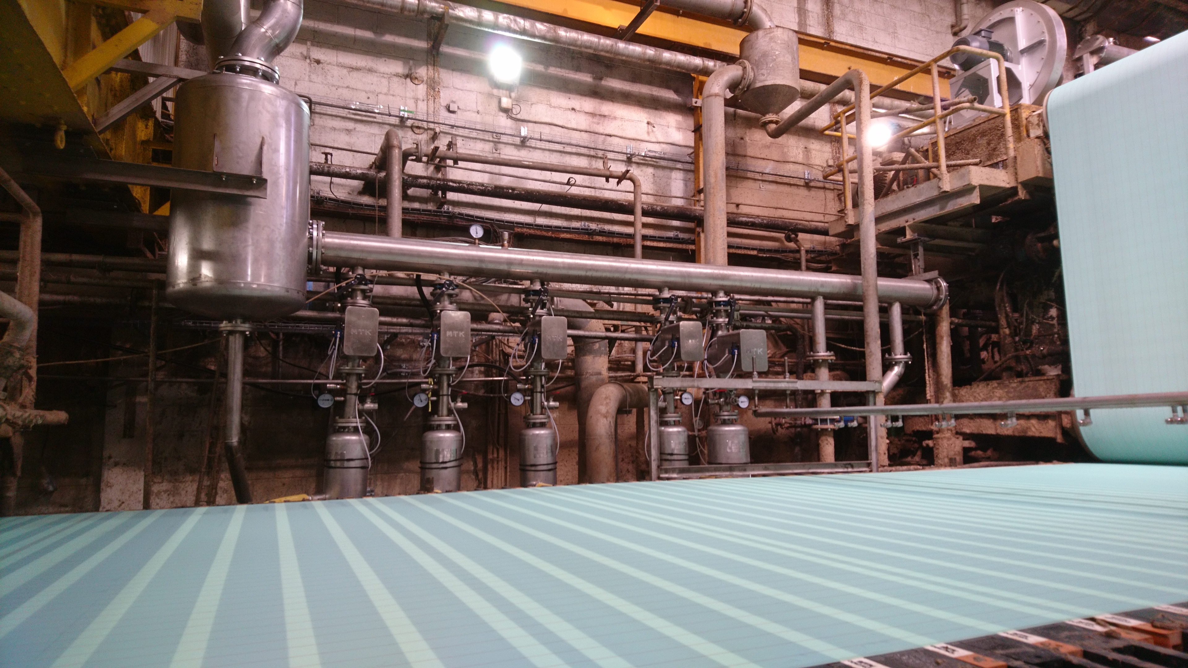
- on-site acquisition of process data (working vacuum pressure of the various suction boxes (canvas area, felt/press area) and conditioning boxes (felt/press area), air speed inside the pipes (where possible), machine speed, paper widths, canvas width, felt, surveys for calculating the suction area of each vacuum element, plate data and operating curves of pumps and fans, type of paper, technical characteristics of the felt(s), water extraction pump plate data;
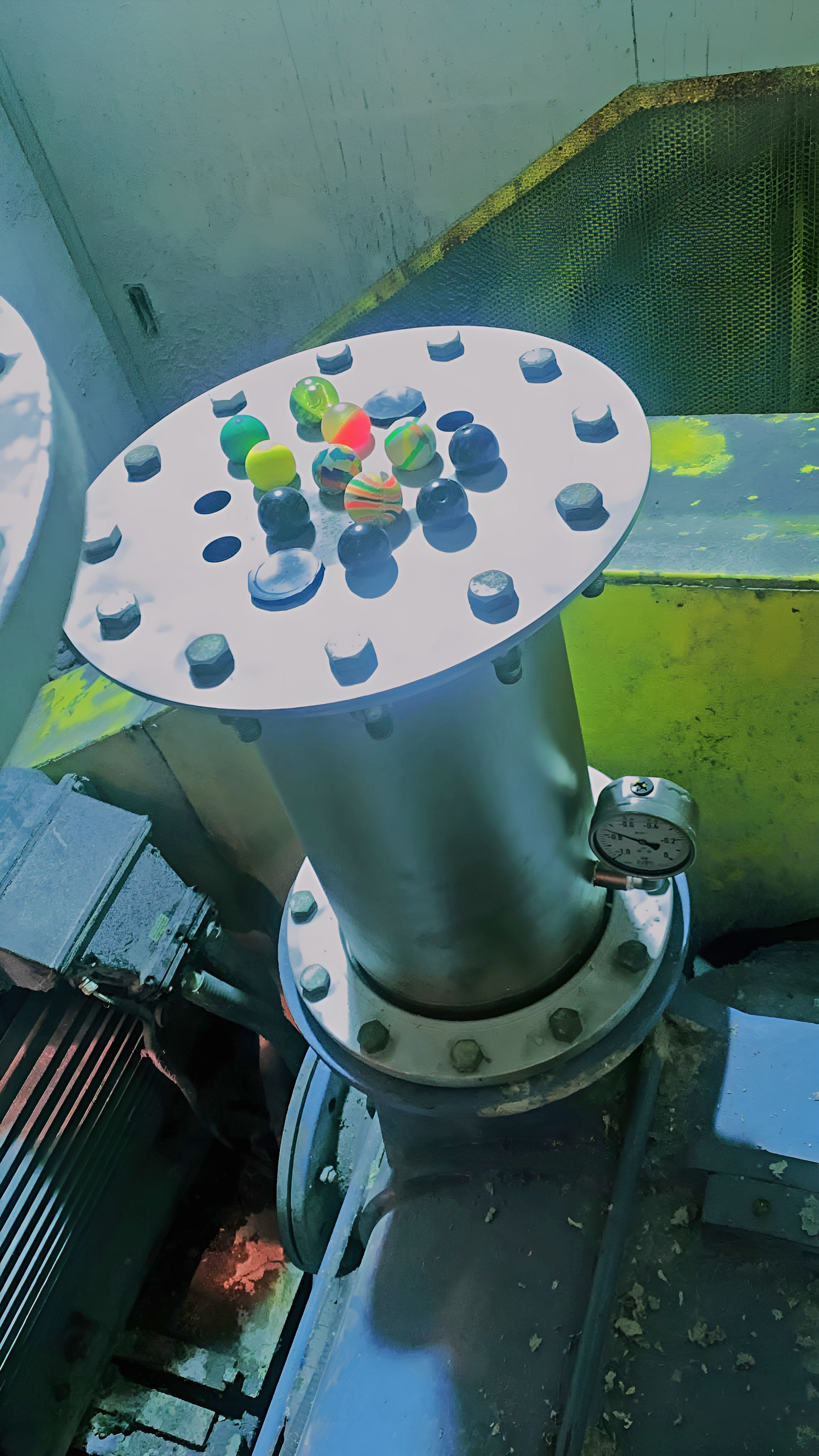
- performance test on fans and pumps, necessary to analyse their operating status, comparing current performance with ideal ones (new conditions). To carry out this test, we proceed to disconnect the pump from the suction pipe that connects it with the continuous machine, then place a perforated plate (test plate) on the suction mouth of the pump (one or two mouths, depending on whether it is single or double stage); then, once the pump is started, close one hole at a time, so to register different engine absorption and vacuum values taken on the intake mouth(s), in order to reconstruct the two real characteristic curves (flow / vacuum pressure & absorption / vacuum pressure) that will be compared with the ideal ones, provided by the manufacturer, to understand if the loss of pump efficiency that is created over time is acceptable or not. If it is not acceptable, it will be necessary to evaluate with the customer a subsequent step of reconditioning or replacement with a new one.
To then elaborate a real curve that displays values of depression and flow rate, we proceed to record the values with open holes, and then progressively clog them, recording the variations.
The comparison between the curve obtained and that originally provided by the manufacturer (with new pump, ideal conditions) allows to evaluate the possible loss of efficiency in operation over the given period; if the efficiency recorded is such as to affect consumption, the revision or replacement shall be carried out.
Results obtained
At the end of the audit activities, a final report describes in detail any problems identified in the plant and indicates improvement solutions in order both to improve the management and to optimize the process as much as possible.
The efficiency intervention usually proposed, in the case of turbo-blowers, allows to derive the maximum benefit where low vacuums are required. For different operating conditions, it is proposed instead to proceed with an optimal adjustment of the liquid ring pumps, reducing the number of revolutions and ensuring a consumption weighted to the required degree of vacuum.
In the event that the vacuum system is rebuilt, the intervention often consist of replacing correctly sized separators, pumps and fans, together with new automatic valves.
Alternatively – if the conditions are not such as to require replacement – it is possible to proceed with the revision of the individual components; in this case, fouling is removed.
Maintenance activities aimed at restoring the optimal conditions of the components of the vacuum system include the sealing of the cracks, which have been created, for example, on the pump head due to cavitation, using a filler resistant to mechanical stress.
Similarly, applying a layer of ceramic paint to the inside of the pump body and impeller can help reduce friction between the water and the metal structure, improving efficiency and preserving surfaces from wear and early deposits.
DCS Vacuum control panel
Vacuum Box DCS (Distributed Control System) is the control system installed in the machine room and managed by line operators who digitally monitor the entire vacuum system of the wire section.
Through the system it is possible to control not only the automatic valves and their settings according to the type of paper production, but also the fans and vacuum pumps. It is also possible to install the consistency sensors right on the canvas and process the data collected directly on the software in order to adjust the vacuum system in an optimized and integrated way, thus reducing energy consumption.
Maintenance activities aimed at restoring the optimal conditions of the components of the vacuum system include the sealing of the cracks, which have been created, for example, on the pump head due to cavitation, using a filler resistant to mechanical stress.
Similarly, applying a layer of ceramic paint to the inside of the pump body and impeller can help reduce friction between the water and the metal structure, improving efficiency and preserving surfaces from wear and early deposits.


